Von Neumann Architecture
The most common architecture for digital computers was first proposed
in 1946 by John Von Neumann - in those days, only mechanical calculating
machines were common. He proposed a machine constructed from cogs and
wheels, devised around 4 essential components - input, output, processing
and storage. All instructions and data to be operated on were to
be stored together (in binary) and were indistinguishable.
This simple model is still the most commonly used model today, even
though it has some SERIOUS drawbacks (which have only really become
apparent due to the high speed and capacity of modern computers).
Some INPUT DEVICES include keyboard, mouse, microphone, stylus, scanner,
bar code reader, optical character readers, magnetic character readers,
plasti-card swipes, digitiser, joystick, punched
card readers...
Some OUTPUT DEVICES include monitor, speaker, printer, plotter,
robotic devices...
Combo peripherals include your sound card, MODEM, tablet/touch screen
Some STORAGE DEVICES include cassette tape, DAT, floppy and fixed
disk, optical disks (CD ROM, WORM drives, CD-RW, MO drives, Minidisk,
DVD) ,ZIP, JAZ, magnetic core, punched cards/tape, USB memory keys, Memory syicks, Flash cards, SDcards, iPods...
The PROCESSING usually is performed (in PC's) by a single CPU (Central
Processing Unit) possibly assisted by a maths co-processor that is either
built-in to the chip, or is an optional extra you buy as an 'upgrade'..
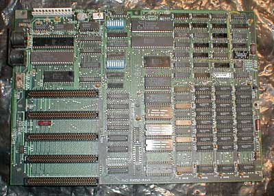
In old-school computer systems, the MOTHERBOARD was little more that a place to plug in other components - the central databus was shared by everything, memory access was physically limited, expansion was torturous.
More modern motherboards contain many integrated features and a wide variety of expansion slots and an even wider range of busses to pipe data around, have much larger memory and processor capacities but are just extensions of the "old-school" model, and as such, share in it's limitations.
Larger systems may have many processors, each connected to memory and
I/O devices - parallel processing
The CPU has an ALU (Arithmetic Logic Unit) that handles arithmetic
operations, and a collection of Programmable Registers, and is connected
to the 'outside world' via BUSs
A BUS is a structure that allows only ONE piece of information on it
at once (byte, word, paragraph depending on DATA PATH WIDTH). The passage
of 'parcels' of info along the bus is rigidly controlled by the system
clock. - results in INFORMATION BOTTLENECK. A bus consists usually of DATA, CONTROL and ADDRESS paths, your computer has many of them, and often transmit data at different speeds depending on where the bus is headed.
Computers spend most of their time moving bytes around. The more that
can be moved around simultaneously partly controls system performance
(the system clock speed and the number and access mode of its registers
being the other factors).
The DATA PATH WIDTH can ultimately affect the performance of a machine.
   8088 = XT (eXtended Technology)        8 bit data path
   8086 also XT                           16 bit (internal)
   80286 = AT (Advanced Technol)          8/16 bit
   80386 =                                32 bit internal
                       SX                 16 bit external
   80486                                  32 bit internal
                       SX                 16/32 bit external
   P5  (the Pentium)                      32 bit internal
                                          32 bit external
   CRAY Supercomputer                     64 bit internal
                                          32 bit external
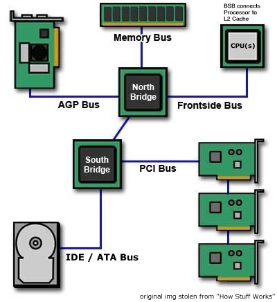
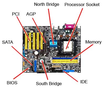
In a "modern" system, the Motherboard provides a number of busses to service the many and varied parts of your computer. The main data highway of your computer is controlled by your chipset, namely the North Bridge and South Bridge.
In general terms, the North Bridge services the processor whereas the South Bridge services the peripherals.
The North Bridge provides a junction for the FSB (Frontside Bus) that leads to the processor, Memory Bus leading to and from RAM and possibly the AGP (Accellerated Graphics Port at 21GB/s) bus feeding your graphics display. In addition, there is a BSB (the processor usually determines this bus speed) linking the processor to it's Level2 Cache, although this may well be on the same die as the processor and therefore really a short fast bus.
South looks after the PCI (Peripheral Component Interface = parallel 66MHz,64bits wide) bus and IDE (Integrated Drive Electronics = parallel 133MB/s max currently) /ATA (Advanced Technology Attachment = serial SATA, parallel PATA, max 150MB/s currently, SATA2 max 300MB/s) bus for peripheral controllers and mass storage.
Much of memory available these days is DDR (Dual Data Rate) meaning it is ready to transmit data twice per cycle, with a dual data bus this means that twice as much data can get to and from the processor each cycle, decreasing the wait time your processor suffers.
Your system may also employ other busses to shift data around, depending on what you have in your case [ ... read more ]
Advanced architectures allow multiple pathways for data and instruction
streams into the processor (the P5 has 2 separate instruction 'pipelines').
The intel series chips (x86's) are all CISC (Complex instruction set
chips - that is they have a large variety of assembler instructions
that the programmer can use with them) - this leads to very low level
programming + 'small' programs.
RISC (Reduced instruction set chips
- with a smaller choice of built-in assembler functions) work faster
than CISC chips (as they spend less time 'looking up' what instructions
mean) but typically, equivalent programs are larger than the CISC equivalents
Data Communication
BUSses commonly employ PARALLEL communication
8 wires = 1 byte (a bit for each wire)
16 wires = 2 bytes
64 wires = 8 bytes .......relatively fast
Another mode of communication is SERIAL ......relatively slow
1 wire -whole byte/word sent through 1 wire 1 bit at a time
Both modes require control logic to instruct the destination that a
transmission is about to start, when it terminates, and whether errors
in transmission have occurred. This control logic is usually sent on
separate wires in parallel comms and as part of the message in serial
comms.
PARALLEL - used to connect components relatively close (due
to huge cost of large number of wires, and increased signal deterioration
over distance).
Ultimately, a parallel connection is limited by skew:
Start                                           Finish
o--------------------------------------------------->
o---------------------------------------------------->
o----------------------------------------------------->
o----------------------------------------------->
o------------------------------------------------------>
o--------------------------------------------------->
                                                <-Skew->
At the beginning of a 100 meter dash, the runners all line up evenly
at the starting line. But they cross the finish in a ragged pattern.
Electrons rush down a wire at almost the speed of light. However, when
there are several wires running any distance between several devices,
the signals don't all get to the end of the wire at exactly the same
time. This is called skew.
Part of the problem are irregularities in the wire itself. One wire
may be thicker than another, and different batches of copper have different
amounts of impurities. Part of the problem comes from differences in
individual connectors every time the signal passes through an attached
device.
Skew limits how tightly the bytes can be packed on the cable. All of
the bits for one byte must arrive at the end of the cable before any
bits for the next byte can arrive. Engineers have to design for the
worst case, so they generally leave a big gap between bytes. As the
cable gets longer and the number of attached devices grows, the gap
has to get wider and the speed of the data goes down. Worse, because
skew is cased by low tech issues (refining copper, making wire, and
building cheap connectors) it is not possible to solve this problem
by building better computer chips.
SERIAL used over long distances - phone lines, microwave, satellite
links etc. due to relative cost effectiveness
The application, usually, determines the transmission speed necessary
and the integrity (or error level) acceptable.
- Telephone (voice) requires 10000 bit/s, and low integrity
- Data (ATM bank transactions say) require 10000 bit/s but high data
integrity - why?
- Text 2400-9600 bit/s with high integrity
- Images (TV, full motion video, HDTV) 5 Mbit/s + (where a 2 hour
video = 2 Gb) with low integrity
Video cards are available that employ a 'local' BUS (IBM clones only
recently offering this feature) - graphical information can be pushed
to the monitor at a greater rate and hence the image is refreshed faster,
and of a higher resolution.
Transmission modes - one way (telemetry), two way alternate (most communication),
two way simultaneous (computer- computer)
SERIAL COMMUNICATION PROTOCOLS
These are mutually negotiated decisions regarding:
- speed (baud) = bits/s
- data unit structure -how many bits represent a character -how many
start bits -how many stop bits -how much rest time between characters
- error detection
- options
- ignore and discard
- detect and retransmit
- detect and correct
- schemes
- parity odd/even (simplest)
- checksums
- sequence numbers
- Timing -referring to BUS timetabling, devices that use the same
system timing are said to be SYNCHRONOUS, those that use different
timing are ASYNCHRONOUS
Connecting devices using a protocol is called HANDSHAKING
ERROR DETECTION
PARITY
The simplest form of error checking involves bytewise PARITY. Using
this scheme, the MSB is used prior to transmission of the byte as a
FLAG. Under EVEN PARITY, as an example, the BIT SUM of
the 7 DATABITS is calculated (ie. the number of 1's are counted)
- if that bit sum is ODD, then the MSB receives a '1' to EVEN OUT
the bit sum. If the bit sum is already EVEN, then the MSB receives a
'0'.
example:
     1101110  under EVEN PARITY would be transmitted as 11101110
     0101101  under EVEN PARITY would be transmitted as 00101101
     1101110  under ODD PARITY  would be transmitted as 01101110
     0101101  under ODD PARITY  would be transmitted as 10101101
At the receivers end, the receiver device merely checks the BIT SUM
of each byte as it arrives, if they agreed on EVEN PARITY, each arriving
byte will have an EVEN bit sum, otherwise an error is said to have occurred
Although widely used, there are many things that could mask a problem
in transmission. 2-Bit damage is impossible to discern (although this
form of damage is exceedingly rare)
CHECKSUMS
Checksums are numbers calculated on the data prior to transfer that
can be recalculated on arrival to verify the data arrived correctly.
There are many schemes for such checking, but what follows is an example
of the ISO Checksum Algorithm
ALL CALCULATIONS are performed within A SINGLE BYTE - what does
not fit is discarded - this is termed Modulo 255 arithmetic.
Bunches of bytes (packets) are transmitted along with 2 checksum
bytes - the calculation of which is described as follows:
Suppose the bytes:  6    15     20    and   1  need to be sent.
This will be sent with 2 checksum bytes X and Y to make a 6 byte packet.
The process for calculating X and Y is as follows:

       6    15    20     1     X     Y
    i= 1     2     3     4     5     6

initially
    A = B = 0; (these are 2 intermediate results necessary)
    X = Y = 0; (these will be the checksum digits eventually)

i=  1  A =  6                   B =   6
    2  A =  6 + 15 =  21        B =   6 + 21 =  27
    3  A = 21 + 20 =  41        B =  27 + 41 =  68
    4  A = 41 +  1 =  42        B =  68 + 42 = 110
    5  A = 42 +  X =  42        B = 110 + 42 = 152
    6  A = 42 +  Y =  42        B = 152 + 42 = 194

    X = -B +  A  = -194 + 42  = -152 = 103
    Y =  B - 2A  =  194 - 84  =  110

so the packet transmitted is:  6  15  20  1  103  110
When the data is received after transmission, part of the above calculation
is repeated, arriving at values for A and B (but instead of using 0
for the value of X and Y, we use the transmitted values). If EITHER
A or B end up being 0 (ZERO) then the transmission was error free.
Suppose we recieved from the above transmission, the following packet:

       6    15    20     1   103   110
    i= 1     2     3     4     5     6

initially
    A = B = 0; (these are 2 intermediate results necessary)

i=  1  A =    6                      B =   6
    2  A =    6 +   15 =   21        B =   6 +   21 =  27
    3  A =   21 +   20 =   41        B =  27 +   41 =  68
    4  A =   41 +    1 =   42        B =  68 +   42 = 110
    5  A =   42 +  103 =  145        B = 110 +  145 = 255 = 0
    6  A =  145 +  110 = 255 =0      B =   0 +    0 = 0
Since EITHER A or B is equal to ZERO, then there was no error
in transmission. The strength behind this method of error detection
is that the Checksum digits are calculated UNIQUE to that packet, so
if any part of the package gets damaged during transmission, the checksums
will not re-calculate correctly:
Suppose we recieved from the above transmission, the following 'DAMAGED' packet:

       6    15    20     2   103   110
    i= 1     2     3     4     5     6

initially
    A = B = 0; (these are 2 intermediate results necessary)

i=  1  A =    6                      B =   6
    2  A =    6 +   15 =   21        B =   6 +   21 =  27
    3  A =   21 +   20 =   41        B =  27 +   41 =  68
    4  A =   41 +    2 =   43        B =  68 +   42 = 110
    5  A =   43 +  103 =  146        B = 110 +  146 = 256 = 1
    6  A =  146 +  110 = 256 = 1     B =   1 +    1 =   2
Using the damaged packet, NEITHER A OR B result in ZERO - therefore
we have detected an error has occurred, but we are no closer to determining
WHERE in the packet that error was.
CONNECTION SPECIFICS
Signalling along copper wires use voltage levels to transmit information.
Disconnect = level 0, a '1' is a relatively high level and a '0' is
a low (but higher than 0 level). Can you suggest why they do not use
Level 0 for a zero?
TRANSMISSION MEDIA
- Telephone lines - 2 million bit/s maximum, high noise, easy to tap,
cheap
- Co-axial cable - 500 million bit/s
- Optical Fibre - 2 Giga bit/s, becoming cheaper, relatively difficult
to line tap, relatively immune to interference
- Terrestrial Microwave - sub 1 giga bit/s - signal deterioration
due to moisture, easy to intercept broadcast
- Satellite Microwave - intensive ground cover, high risk, limited
life (av 15 years), signal delay 1/2 sec and interference due to weather
Common Communication Standards
- POTS (Plain Old Telephone System) - data speeds of 33.6Kbps are
now common
- ISDN - data speeds of 54-56Kbps per B channel. Using 2 B channels,
it is possible to get speeds up to 128Kbps. Using 24 Channel ISDN,
1.5MBps is possible.
- Frame Relay data speeds often exceed 1.54MBps
- T1/DS2 = 1.54Mbps, DS2 = 6.312Mbps, SMDS/DS3 = 56Kbps up to 34Mbps
- STS-1 (currently the 'top' specification) is capable of speeds up
to 51.84Mbps.
Voice communication (through phone line, say) is sent ANALOGUE to local
exchange. There it is sampled 8000 times a second, the samples are converted
to 4 bit binary, stuck together in sequence, packaged up with control
bits into a packet and then sent DIGITALLY (via a complicated
protocol) to the destination local exchange. There it is split up, and
converted back into ANALOGUE. Most local exchanges use TONE dialling
(digital 'beeps') as opposed to PULSE dialling (analog 'clicks') to
set up the connection between source and destination.
Computer communication over a phone line can be achieved via a MODEM.
This device MODulates the digital output of the source computer (into
analog sounds). At the other end it DEModulates the sounds (into digital
1's and 0's).
Transmission via modem is usually asynchronous and serial