The Keyboard
In 1872, an inventor
called C. L. Sholes devised an arrangement of letters for a typewriter
that slows typing, encourages errors and fatigue and places convenient
keys in inconvenient places. This was necessary as the mechanical typewriting
machines that were state of the art then were klunky and jammed often
if you typed too fast. The arrangement of letters that starts with QWERTY
is C. L. Sholes invention and it is still in use on most computer and
typewriter keyboards today. There are many alternatives to the QWERTY
layout - in 1930 August Dvorak devised an alternative that has proved
in several tests to allow much faster speeds with a higher degree of
accuracy.
What sort of marketing
campaign would be necessary for the world to convert to DVORAK given
they are already familiar with QWERTY? I doubt even Microsoft could
successfully market that idea (even though the idea is actually a good
one - unlike many from that American company).
Every key on the
keyboard generates at least one 7 bit SCAN CODE when you press it. Some
special keys (the function keys, for example) generate two such codes.
These scan codes
are used by the computer to differentiate your keyboard intentions.
Additionally, a 1 is placed in the MSB of the scan code when it is pressed
(MAKE), and a 0 is placed in the MSB when it is released (BREAK) - this
way the computer can tell when you press and release (or indeed hold
down) a key.
   eg.  "a"  = 30(dec)  =  10011110    make
                        =  00011110    break on release


   eg.  "A"             = 10110110     make right-shift
                        + 10011110     make "a"
                        + 00011110     break "a"
                        + 00110110     break right-shift
There are also in
primary memory 2 KEYBOARD STATUS BYTES which store the current state
of the keyboard (ie. whether the numlock or capslock is on, if the ctrl
is pressed... etc). The state of the Keyboard status bytes determine
the overall effect of the keypress.
Scan codes are bussed
to the CPU. If the CPU is told (by an intermediary chip) that the keypresses
are of a higher priority than the CPU's current task, it first pushes
its registers onto the stack. The CPU then checks the keyboard status
bytes to determine the overall effect of the keypress, then looks up
the key combination to turn the code into ASCII if appropriate - this
character is then placed in the keyboard buffer, break scan codes are
discarded. If there was a delay (hardware/software configurable) before
a corresponding break scan code is received, the CPU generates multiple
copies of the ASCII sending them to the keyboard buffer as well.
The keyboard buffer
is a circular queue (FIFO structure). When the keyboard buffer is full,
extra key presses are discarded (along with a warning beep).
Software interrupts
allow the CPU time to inspect the keyboard buffer and process ASCII
codes waiting there - if they are printing characters they may be sent
to video RAM which then appears on the screen.
Characters are displayed
in 2 byte form (in text mode) - 1 byte for the ASCII, and one byte for
the attributes (color, blinking, bold...
Some Common Peripherals
A PERIPHERAL is
a device that can be attached to a computer (and therefore be used by
it). Most peripherals require particular INTERFACES (ie. connection
types) and use specialised signalling and fast protocols to allow rapid
data interchange
- Cassette Recorder
This device used to be used as a STORAGE unit for early personal computers.
To SAVE a program or stream data out, you needed to have RECORD on
the tape player, to LOAD programs or data back in to the PC, you PLAYed
tape. This was SLOW, SEQUENTIAL ACCESS and ANALOG (ie. Digital data
was converted into SOUND on record, and back again on PLAYBACK) and
often whole programs were lost by accidentally recording over the
start or end sequences on poorly marked tapes.
- Joy Stick
Used mainly for interacting with GAMES, the joystick of today allows
the recording of relative movements in any direction, along with the
transmission of game switches (like fire, jump...)
- Mouse
Allows the recording of relative positions, used to control a number
of graphical pointing devices, One, two or three buttons are common.
- Digitising/Graphics Tablet
Graphic artists usually find a Mouse to be an unnatural drawing tool.
A pressure sensitive surface that can be drawn on using a stylus is
a popular alternative. Digitising tablets are able to translate the
relative position of the stylus into a set of XY Coordinates which
can then control a pointing device on a graphical system.
- Scanner
Flat-Bed and Hand Held scanners are commonplace now, available in
MONOCHROME (B&W) and FULL COLOUR. MONO scanners sample the image they
are given at pre-determined resolutions, producing a stream of BINARY
data that breaks the image into scan lines of pixels. Colour scanners
typically SCAN the image taking 3 or 4 readings at a time, each pass
detecting the relative intensities of each of the colours RED, GREEN,
BLUE, then combining that data into a colour image bit stream for
display.
- Plotter
A Plotter is typlically used for producing high definition technical
drawings, and harnesses a series of pens that are moved across the
surface of the paper in all directions - an image is built up by drawing
sections of lines, curves and text in the order specified by the graphics
program.
- Printers
- Daisy
Wheel
A print wheel is fitted to a stepping motor, which can with great
accuracy (and usually a lot of noise) rotate the wheel to the
correct character prior to an electromagnetic HAMMER pounds tha
wheel leaving a carbonised ribbon imprint on the paper. By varying
the WHEEL, different fonts are attainable. A daisywheel printer
is typically unable to reproduce graphics.
- Dot Matrix
The print head is a line of 9 or more metal PINS that can be programmed
to extend or retract whilst the print head moves left to right
and back again. A Dot matrix printer builds up it's image by repeatedly
passing left to right, varying the pin positions as it moves.
The image is transferred to paper by a carbonised ribbon that
the pins strike when extended. Dot matrix printers are able to
render graphics with a number of factors depending the quality
of the resultant image (closeness of pin strikes, size of pins,
responsiveness of ribbon etc.). Colour Dot Matrix printers use
special ribbons with each of the colors CYAN, MAGENTA and YELLOW
(and usually black) and overprint rows with varying mixes of these
colours.
- Ink-Jet
Inkjet printers are similar to Dotmatrix printers with the main
difference being they 'spit' tiny droplets of ink directly on
to the paper using a set of high precision nozzles.
- Laser
Laser printers harness a number of technologies to render images
on paper- typically, a fine lazer is used to 'draw' the image
on an electrostatically charged print drum (such that the parts
of the image that are to be coloured are statically charged and
the background is not). Toner powder is then sprinkled on the
drum, adhering to the charged areas. The drum is then rolled onto
a page of paper, transferring the toner pattern to the paper,
this paper passes through a FUSER (which essentially bonds the
toner to the paper), the stable printed page is then ejected from
the printer.
- Print Buffers
Most printers use BUFFERS to store the data they are working on
at the time - this allows the computer to stream a job to the
printer and then carry on doing something else whilst the printer
(usually one of the slowest peripherals attached to it) gets around
to completing the job. Network printers usually have print queue
buffers also to allow more than one person to print to the printer
at the same time.
- Microphone
Soundcards these days are capable of sampling audio data at very high
rates, converting analogue soundwaves into digital soundbytes. Microphones
can be used in the place of mice and other input devices for those
with mobility problems, for dictation and music mixing etc.
- Robotic Devices
Movements of robotic devices (and other control technologies) can
be though of as OUTPUT peripherals, translating instructions into
cues for movement. Control technology is gaining wide use in industry,
medicine and electronics.
Secondary Storage - Disks and Drives
Note: we will only consider MSDOS conventions for info storage (some,
however are cross-platform standards)
General

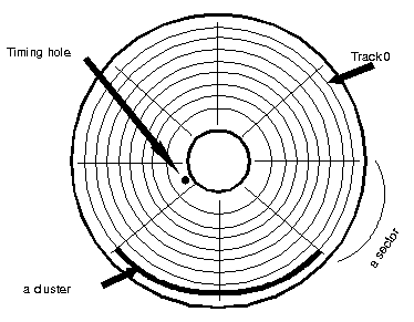
An UN-FORMATTED
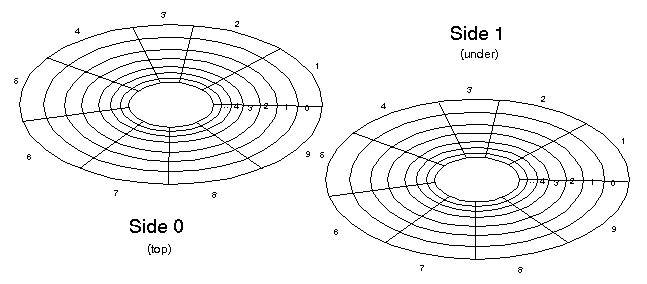
disk has no sensible magnetic patterns recorded on its surface. FORMATTING
a disk involves setting up many concentric rings of organised magnetic
information called TRACKS. The disk surface is also subdivided (pie
like) into wedges called SECTORS. Depending on the system (and the version
of DOS, one or more contiguous track-sector combinations is termed a
CLUSTER or ALLOCATION UNIT
FLOPPY DISKS
- Common sizes
- 8", 5.25" and 3.5" disks
- Composition:
flexible circular plastic disk with magnetic coating then polymer
overcoat on both sides of the disk, in plastic jacket. Magnetic coating
can be altered by magnet (disk read/write head).
- Speed: Rotate
100 - 200 revs/min (any faster and the disk distorts like a pizza)
- Typically, 1
sector = 512 bytes
5.25" 80 tracks,
15 sectors, 2 sides = 1.2 Mb
40 tracks, 9 sectors, 2 sides = 360 Kb
3.5: 80 tracks, 18 sectors, 2 sides = 1.44 Mb

Retrieval speeds:
'access time' determined
by
- seek time = time
to move heads to specified track
- latency = time
to move platen to specified sector
- transfer = time
to transfer data into input/output channel
'Floppies' are relatively
slow, compared to other media (except audio tape). Retrieval speeds
may also greatly be affected by the disjointed nature of the information
on the disk (fragmentation of file)
FIXED 'HARD' DISKS
Composition
typically glass
or metal alloy platen with magnetic coating then polymer overcoat. May
be more than one disk in unit, sealed to be dust free.
Speed
typically rotate
3600 revs per minute or more
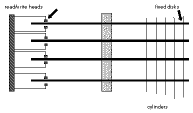
Each disk has sectors
and tracks, with each side of the disk having its own read/write head.
Since all heads are attached to one 'arm', all tracks and sectors are
aligned down through the stack of disks.
Sectors at the same
distance from the centre spindle are called CYLINDERS. Groups of adjoining
cylinders are often termed PARTITIONS.

a 10 Mb Hd might
have 17 sectors, 306 cylinders, 4 heads (ie. 4 platen surfaces)
= 17 sectors x 306 cylinders x 4 sides x 512 bytes/sector
= 1065369 bytes (= 10 Mb ish).
Hard disks suffer
from a problem called interleaving - where the disk is moving so fast
that the read/write head gets to the right place but the disk has moved
before it can get there - therefore connected areas of data are 'staggered'
on the disk surface to avoid having to wait for an extra revolution
when reading contiguous sections of data.
Disk Organisation
Before a disk can
store information, it may be partitioned (using fdisk.com if it is a
fixed disk), then it must be divided into tracks, sectors (called formatting).
There are two levels of format - a low level format (performed by bios
- supporting a wide range of format options), and high level format
(performed by the format.com file, or similar utility) supporting a
relatively limited range of format options.
BOOT SECTOR
May contain an initial program loader and a 'bootstrap' program (that
can load the majority of the operating system into memory and transfer
control to it), and a Boot Signature - this indicates that the sector
contains the 'bootstrap' program and therefore is a 'bootable' disk.
FAT - (File
Allocation Table) - this works with the directory, in keeping track
of the clusters associated with the files stored on disk. The directory
contains the address of the first cluster of a file, the FAT records
each successive cluster (each of the 1 Kb 'chunks' of the file). Files
are terminated with a special entry - called an EOF (end of file marker).
The 'chunks' that constitute a file are termed a cluster chain.
ROOT DIRECTORY
- The root directory is the parent of all other directory entries on
the disk. It contains 32 byte entries recording information on all the
files in it, namely:
filename, extension,
attributes, time and date of save, starting cluster address, and file
size (total). Attributes may be whether the file is a sub-directory,
if it has been backed-up, hidden, system, read only...
Hidden/system files
do not appear on a normal directory listing
A Fixed disk must
have a BOOT SECTOR, FAT's and a ROOT DIRECTORY for each of its PARTITIONS
(if more than one)
Cluster Sizes
The size of a CLUSTER
can vary due to a number of factors including Disk Capacity (more correctly
PARTITION SIZE) and Operating System. Since a CLUSTER is the smallest
size a file can be saved as on that system, the size of the cluster
can greatly effect the storage capacity of the hard disk (or rather
effect the WASTED SPACE on that media)
Under DOS and W95,
Cluster sizes apply on the partition sizes listed:
- less than 256Mb
- 4Kb clusters
- Between 256Mb
and 511Mb - 8Kb clusters
- Between 512Mb
and 1023Mb(1gig) - 16Kb clusters
- Between 1024Mb(1gig)
and 2047Mb(2gig) - 32Kb clusters
- Bigger than that....?
Not all operating
systems are so restricted - Under NTFS (The Windows NT File System),
all clusters are 4Kb regardless of the partition size.
When buying BIG
(ie. 100-200Gb) Hard Disks, the balance between Partition Size and Cluster
Size is worthy of thought, since, especially if you save lots of very
small files, your wasted (unrecoverable) space is significant.
OTHER STORAGE MEDIA
Although data transfer
to and from OPTICAL drives are signifigantly slower than fixed
media like Hard Drives or Flash Cards/ROMs, typically the storage capacities
are huge.
Conventional CDROM
(Compact DiskROM) can store approx. 640Mb of data (equating to approximately
70Mins of audio data. The reflective surface of a CDROM is orgainsed
into a single SPIRALLING track made up of minute 'pits' (that act like
light traps) and reflectors to represent 1's and 0's.
CDROM retrieval
speeds are improving all the time, with 8 speed being common now. Single
Speed CDROM can deliver data at approx. 150Kbps. a 4xCDROM can deliver
data at approx. 600Kbps, 8xCDROM at 1200Kbps. Average seek time for
a single speed CDROM ranges between 195-250ms.
WORM drives
(Write Once Read Manytimes) are also optical (or Floptical) disks, and
allow the storage/archiving of data without the ability to edit it later.
CD-RW drives are also becoming popular, allowing multiple write
sessions
DVD (Digital
Video Disk or more recently Digital Versatile Disk) is an emerging standard
(with access speeds comparable to a 9-speed CDROM), with DUAL SIDE,
DUAL DEPTH technology using 2 read/write heads and a semi-transparent
over a totally reflective layer. Each DVD layer has a capacity of 4.7Gb,
with a 2 layer, 2 side DVD totalling 17GB of storage space. DVD Writable
have a slightly diminished storage capacity (5.2Gb) due to the decreased
data density possible with PC style read/write heads.
IOMEGA ZIP
Disks can store up to 100Mb or 200Mb per disk cartridge, with access
times approximately 3 times faster than a floppy, they are useful for
transportation of multi-megabyte files between systems. JAZ Drives
offer larger storage capacity (1Gb or more) and again offer removable
storage with multi read/write capability.


